
The power supply module has been designed for the four-wheeled mobile robot. It provides necessary voltages to other robot modules, like +3.3V or +5V but also protects the robot battery.
The power voltage from accumulators has been divided into three separate lines. The first line supplies the motors, so it is a high-currents line. The second line provides power to the DC-DC impulse converters which supply the logical units (3.3V, 5V). Finally, the third line is the additional +5V line that uses a linear stabilizer (LDO) to supply the system for battery protection and monitoring.

The first part of the power supply scheme
DC-DC converters
The module is equipped with two DC-DC converters based on the integrated circuits ST1S10 produced by STMicroelectronics. These converters decrease input voltage to +3.3V and +5V. The design of converters is based on the ST1S10 Application Node.
Power switches
To turn on/off the external robot modules from a high-level control unit (in the case of the mentioned robot it’s a Raspberry Pi), additional power switches have been added to the board. More details about the power distribution in the mentioned mobile robot can be found here. The switches are based on MOSFETS: IRLML6402 for lower currents and Si7141DP for higher currents, especially for the motors controller.
Reverse polarization, overcurrent, and overvoltage protection
The module has been equipped with multiple battery protection systems like reverse polarization, and overcurrent or overvoltage protections. Also, it contains the circuit that should shutdown the robot in case of a low battery charge state, just to protect the battery.
The protection against reverse polarization is based on the unipolar MOSFET N. As mentioned, lines have been also protected against the high current with glass fuse on the motors power supply line and polymer fuses on the low-current lines. Also, all logic lines intended for the high-level control system unit are protected with Zener diodes in case of voltage spikes or just overvoltage.
Battery protection – low charge state
To protect the battery against the total discharge, the power supply unit has been equipped with an additional system. This system cut off all external modules connected to the power supply when the input voltage value drops below a specified level. It is based on hysteresis, so it turns off modules when the input voltage is below 9.3 V and turns on again if it’s above 9.6 V.
A possible extension for this module could be the soft-stop system to ensure the safe turn-off of all modules.
Battery state indicator and battery voltage measurements
Another feature is the battery state indicator. It consists of three LED diodes. However, it’s placed on the power supply board, so its role is rather limited to robot debugging purposes. The more important from the user perspective is the voltages measurement system. It allows reading of each voltage of the power supply by I2C interface. By each voltage I mean the voltages in each cell of two batteries but also the lines intended for the other modules.

Another part of the power supply module unit scheme – voltage measurement system
Visualization of the power supply module
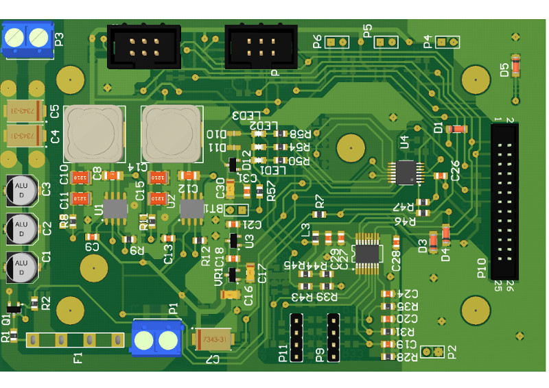
Visualization of the power supply module – top view

Visualization of the power supply module – bottom view