Lidar-based odometry for mobile robot (0-10 points)
Goal
The goal of this task is to implement a basic LiDAR-based odometry system for a mobile robot. The system should estimate the robot’s motion by matching consecutive 2D LiDAR scans and compare it with wheel encoder odometry. This lab focuses on understanding scan conversion, matching, and pose estimation, and visualizing results in RViz2
Description
Create a ROS 2 system that estimates the robot’s motion using LiDAR scans. The system should include the following components:
- LiDAR scan converter and matcher
- Odometry publisher
- RViz2 visualization node or configuration
The structure of the system is shown in the diagram below:
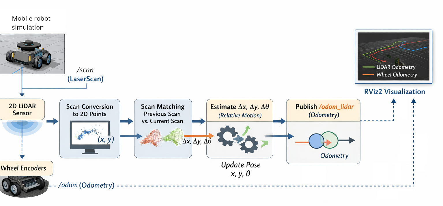
LiDAR Scan Converter and Matcher
- Subscribe to the
/scantopic (sensor_msgs/LaserScan). - Convert each scan into 2D Cartesian points
(x, y). - Store the previous scan to match with the current scan.
- Implement a simplest scan matching algorithm:
- Compute the centroid of points in each scan.
- Estimate relative translation Δx, Δy between scans.
Odometry Publisher
- Maintain a running estimate of the robot’s pose
(x, y, θ). - Publish the LiDAR-based odometry on
/odom_lidar(nav_msgs/Odometry). - Subscribe to wheel encoder odometry on
/odomfor visualization only. - Both
/odom_lidarand/odomshould be visible in RViz2.
RViz2 Visualization
- Visualize:
- LiDAR odometry path (
/odom_lidar) - Wheel encoder odometry path (
/odom)
- LiDAR odometry path (
Remarks
-
Parametrize node parameters (e.g., scan rate, update frequency) in YAML files.
-
Create a ROS 2 package containing:
- Python node(s) for scan matching and odometry
- Launch file to start odometry and visualization nodes:
ros2 launch package_name launch_lidar_odometry.py
-
Document your code. Include explanations for your scan matching algorithm and coordinate transformations.
Resources