
I would like to introduce a sensorless BLDC motor controller based on a 16-bit Freescale MC9S12A64 microcontroller. The controller is a part of a bigger project related to BLDC motors research, so the size minimalization was not a key feature. The whole project contains also the measurement unit used for the supervision of the motor control process.

Software
The software has been written in C, in Freescale Code Warrior environment which is based on the Eclipse.
Algorithm
The algorithm uses the finite state machine (FSM) idea. Transitions between states are triggered by microcontroller interruptions in most cases.

Shortly after the device start, the peripheral modules are initialized, especially ADC, timers, signals generators, or I2C interface.
Then, to motor start procedure is executed. It depends on the execution of the consequent commutation with decreasing the time between them. It in most cases allow to achieve a higher rotational velocity of the motor that is necessary to induce a back electromagnetic field (EMF). Then the control mode is switched to the back EMF-based. The back EMF is measured accurately to estimate the current motor shaft position.
To increase robustness, an additional watchdog module has been used to trigger the start procedure in case of issues.
Time of the next commutation
The calculations of the next commutation time are based on the voltage measurement of a specific motor’s winding.
If the measured voltage value is above half of the input voltage, then we know that the time of the next commutation from now should be the same as the time from the last commutation till now. So, it can be simply calculated and then measured by one of the microcontroller’s timer.
PID controller
The PID controller has been used to control the motor rotational velocity. The output of the controller is a PWM duty cycle. The input is the difference between the set value and calculated rotational velocity based on the magnetic encoder AS5040 measurements. The transfer function of the PID controller is as follows.
K_R(s) = K_p ( 1 + 1/(T_i s) + T_d s )The PID controller is tuned by a dedicated user application.
Rotational velocity measurement
To measure the rotational velocity of the motor shaft, the magnetic encoder AS5040 has been used. Based on the two quadrature signals from the encoder, shifted in phase, the rotational velocity and direction is estimated. The used method is based on signal ticks counting in a specified time period. However, such a method is not very accurate when the rotational velocity is low.
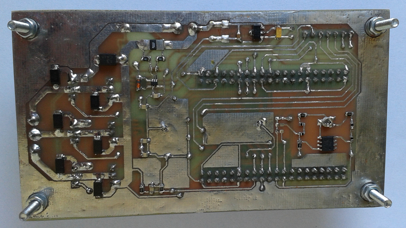
Hardware
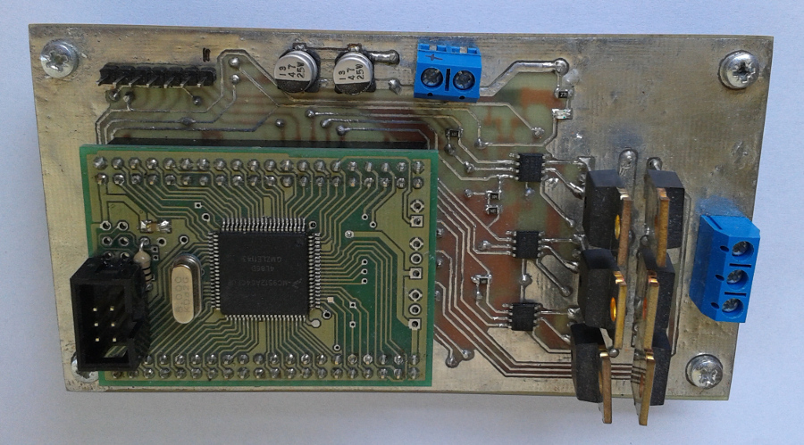
The hardware has been designed to cooperate with the ready module with MC9S12A64.
Power supply and current measurement circuit
The device needs DC power supply in the range from 8 V to 15 V. To protect the device against high-energy voltage spikes it was used two protection diodes transil (TVS1, TVS2).
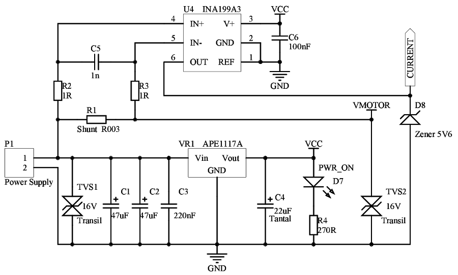
As the energy reservoir, two electrolytic capacitors were used – C1, C2. Two capacitors connected in parallel, decrease the equivalent series resistance (ESR) what have a positive impact on the frequency range of filtrated of noises. The R1 resistor of value 3 mΩ with INA199A3 IC (U4) have been used to measure the current consumed by the motor. The output of the measuring amplifier has been protected with Zener diode (D8).
Current measurement resolution
It was used a 10-bit analog-digital converter (ADC) with reference voltage V_REF=5 V. The resolution of the measurement is as follows
V_{RES} = \dfrac{V_{REF}}{2^{10}} = 4.88~mVOn the other hand, the resolution of the measured current is the following.
I_{RES} = \dfrac{V_{RES} \cdot R}{K} = 8.13~mAReference voltage
To increase the accuracy of the analog measurements, it was used external source of the reference voltage, IC LM336D-5.0. However, the user can select the source of the reference voltage by the appropriate jumper. Only one jumper can be closed at once to avoid device destruction.
- J1 closed – 5 V from the stabilizer.
- J2 closed – input voltage divided by the voltage divider.
- J3 closed – 5 V from the LM336D-5.0.

Connector to the module with MC9S12A64

Voltage measurements – analog circuits
To adjust the measured phase voltages, the voltage dividers and low-pass RC filters were used. Resistors values were calculated to no exceed the 5 V on the output. On the other hand, RC filters were tuned to cut off the frequencies related to the PWM signals.

Measurement resolution
The resolution of the voltage measurement for the 10-bit ADC is as follows.
V_{RES} = \dfrac{V_{REF}}{2^{10}} = 4.88~mV
Based on the voltage divider equation,
U_{out} = U_{in} \cdot R_2 / (R_1 + R_2)
the resolution on the voltage divider input is as follows.
V_{RES2} = V_{RES} \cdot (R_1+R_2) / R_2
For resistors values R_1 = 2.2k Ω i R_2 = 4.7k Ω it is.
V_{RES2} = 0,00488 \cdot (4700 + 2200) / 2200= 15~mV
Of course, the calculated values depend on the resistors tolerance.
The power stage
The power stage of the controller consists of the unipolar MOSFETs with N channel (Q2, Q4, Q6) and P channel (Q1, Q3, Q5). To change the MOSFETs gates quickly additional drivers were used (U1, U2, U3). It works as follows. The microcontroller generates six independent PWM signals which are passed to the drivers (U1-U3) inputs. Then, drivers charge MOSFETs gates to control the motor phases. To decrease the load of the MOSFETs parasitic structures, additional diodes (D1-D6) were applied.

Connector for the measurement unit
Signals are as follows:
- I2C lines – communication interface
- U_PHASE, V_PHASE i W_PHASE – measured voltages on three phases of the motor
- CURRENT – measured motor current
- A_LSB_U – output of the incremental encoder. Already not used but can be used in the future for more advanced control methods tests.

Communication with the measurement unit
To communicate the controller with the measurement unit the I2C interface has been used. In this case, the controller is a slave device and the measurement unit is a master device.
References
- Marek Kabała, Marek Wnuk. Moduł z mikrokontrolerem MC9S12A64
- AVR444: Sensorless control of 3-phase BLDC motors based on tinyAVR and megaAVR devices
- MC9S12DJ64 Data Sheet