
I would like to introduce one of my projects related to motors control. It’s a three-phase (3F) brushless DC (BLDC) motor controller based on the AVR ATmega8 microcontroller.
Features
- The motor shaft position is estimated based on the induced back electromagnetic field (EMF) which allows to get rid of additional shaft position sensors.
- Start procedure allows running motor only if the initial load is small enough.
- Two control modes:
- speed control with feedback loop and PID controller,
- control without feedback loop.
- Rotational speed calculated based on the time between commutations.
- Supported 3-phases BLDC motors with windings connected in a star.
- Power stage based on MOSFETs.
- Input voltage in the range of 8-13 V to use it with three cells Li-Poly battery.
- Continuous current up to 8 A.
- I2C communication protocol.
- Limited max motor current.

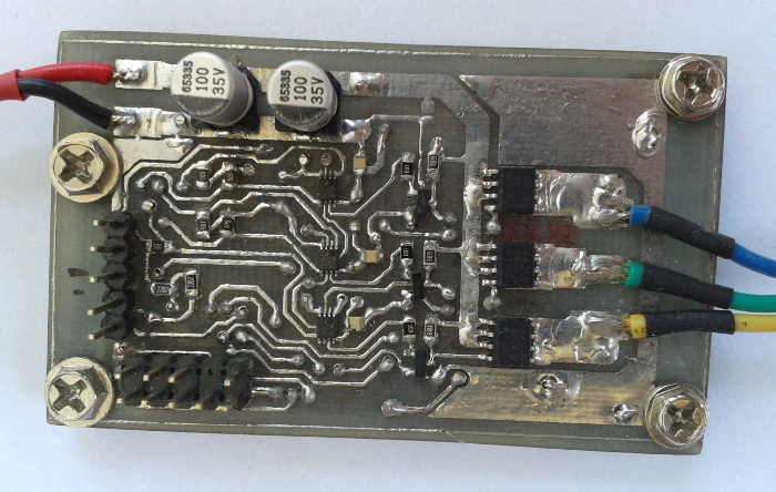
Motor controller visualization
Input circuit with filters and stabilizer
To filter out some noises from the supply voltage, two electrolytic capacitors C1, C2, and ceramic capacitor C3 were used. The role of the C3 is to filter out high-frequency voltage spikes. The LM1117-5 stabilizer has a maximum VDO (Voltage Dropout) equal to 1.1 V when the current value is below 100 mA.

Input circuit with filters and stabilizer
AVR ATmega8 microcontroller circuit
The ATmega8 microcontroller is equipped with multiple GPIO (General Purpose I/O), ADC (Analog-Digital Converter), and timers, necessary for the motor control. Additionally, it has an I2C controller and dead time generator especially helpful in MOSFETs control.

Microcontroller ATmega 8 circuit
The idea behind the starting procedure is as follows. During the motor controller starts, the windings are powered in an arbitrary selected order to move the
shaft. That’s because when the rotational speed is low, the back EMF is not big enough to be measured accurately. When rotational speed is enough then the control mode is switched to one based on the back EMF measurements.
Then, the algorithm is based on the assumption that only two windings (phases) are powered at each step and EMF is induced on the third winding. This induced EMF is called back EMF and it has a trapezoidal shape because of the motor mechanical design. The value of induced EMF is proportional to the motor shaft position. Also, based on the EMF measurement commutation times are calculated.
Three lines from the motor (U_ADC, V_ADC, W_ADC) were connected to the ADC of the microcontroller. Moreover, it was used signal SPEED_REF which is a set speed as an analog value. The CURRENT signal is used to measure the current flowing through the motor. As a reference voltage, it was used VBAT divided on the voltage divider. Such a solution allows to avoid the measurement of the power supply voltage before phase voltages measurements. More details can be found in application note Atheml AVR444.
Voltage divider with low-pass filters – a part of the sampling system
To measure correctly induced back EMF in the unconnected winding, the below system has been designed. It consists of four voltage dividers with passive low-pass filters.

Sampling system – low-pass filters with voltage dividers
The element values are calculated to not exceed the microcontroller power supply voltage and AVCC voltage.
Power stage
The power stage circuit can be divided into two parts. The first one is responsible for proper control of the second part with three half-bridges.

A power stage circuit
The device requires multiple PWM (Pulse-Width Modulation) signals to control MOSFET transistors in half-bridges. However, the used microcontroller was able to generate only three such signals. Because of that, an additional module NC7WZ08 with AND gates was used. In used, bipolar control method one PWM signal drives two power transistors.
To control the top transistors of half-bridges it’s necessary also to provide an additional circuit with bipolar NPN transistors. As power transistors two kinds of elements were used, Vishay Si4425DDY for the top side of the half-bridges and Si4162DY for the low side. Another element which is the resistor R18 was used to measure the current consumed by the motor.
Summary
In the current version of the BLDC motor controller, few issues have been noticed. First of all, the start procedure needs some tuning, especially for higher set values. Also, the accuracy and speed of ADC are not very good which makes harder the proper control of the motor.
Nevertheless, it was my first designed and created BLDC controller. It’s fully operational, the motor can be controlled maybe not very accurate but good enough for some applications. That is also related to the used method of shaft position estimation, based on the back EMF measurements. To improve accuracy and to allow motor start with a higher load it has to be equipped with additional positon sensors, for example, magnetic encoders.

Hello, I have a bldc motor that I think is 310 dc. It consists of 36 coils and 12 magnets. I want to make a driver for it. Can you guide me? Thank you in advance.